Substructure Design/Analysis
The Substructure Design / Analysis supports analysis and design of reinforced concrete bridge substructures and foundations by LRFD specifications.
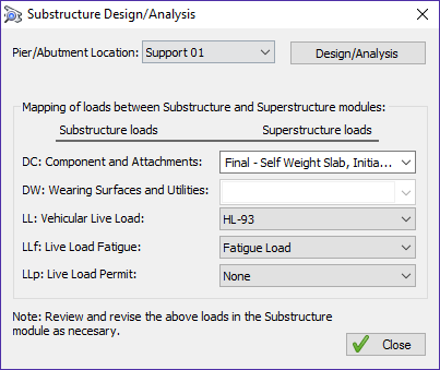
Select the support to be analyzed from Pier/Abutment Location drop-down list, select the dead and live load reaction cases to (optionally) be transferred from superstructure to substructure and press the Design/Analysis button. The LBC Substructure interface is opened with the pier/abutment model loaded.
Remember that after support geometry is completed in LEAP Bridge Steel – Substructure dialogs and is passed to LBC Substructure no other changes in geometry input are allowed. To change something you need to go back in LEAP Bridge Steel substructure input dialogs.
LBC Substructure allows design of multi-column and hammerhead piers, straight, tapered, inverted T or variable caps, and circular, rectangular and variable columns.
Footing types include rectangular isolated or rectangular, circular shaft supported on either soil or piles.
LBC Substructure automatically generates live, dead, wind, seismic and vessel collision loads for analysis, and alerts you if the current design does not satisfy local code criteria. In addition, the program analyzes all other AASHTO load types including centrifugal forces, longitudinal shrinkage, and temperature effects on the structure. LEAP Bridge Steel currently does not pass live and dead load reactions to LBC Substructure. As mentioned above, these loads can be generated from within LBC Substructure using information on spans and members that are passed to LBC Substructure.
LBC Substructure gives a broad range of analysis options to choose from, including P-delta analysis, moment magnification or analysis without slenderness considerations.
Note that in LBC Substructure, the STM is only available for hammerhead piers and isolated pile caps.
LBC Substructure assumes that strut-and-tie locations will be the centroid of provided reinforcement.
LBC Substructure generates analysis results plot diagrams and other printouts. Files may also be exported to spreadsheet format.